The core principle, is that your actual usable power will be limited by the lower of the two components: the solar array’s maximum power output or the inverter’s maximum input power capacity. This isn’t just about nameplate ratings; it involves a complex interplay of electrical characteristics and environmental factors that effect how your solar system works.
1. The V x A Equation and Nameplate vs. Real-World Power
Where P=V×A. While simple, this formula underpins all power calculations.
- Nameplate Ratings (STC): Solar panel datasheets typically provide power ratings under Standard Test Conditions (STC):
- Irradiance: 1000W/m2
- Cell Temperature: 25∘C
- Air Mass: AM 1.5 These are ideal lab conditions. Your system will rarely, if ever, operate exactly at STC But you can be above or below and they should only be used as a guide.
- Real-World Power: The “Lower Limit” Principle:
- Inverter’s Maximum DC Input Power: Every inverter has a specified maximum DC input power. Exceeding this can lead to the inverter “clipping” (limiting the power output to its maximum capacity), operating inefficiently, or even shutting down to protect itself.
- Solar Array’s Maximum Power Output (Pmax): This is the sum of the maximum power points (Pmp) of all panels in the array. However, as we’ll see, this Pmax is highly variable.
2. Temperature Effects: The Silent Power Thief
This is a critical factor often underestimated. in this example of 30∘C ambient leading to 42∘C panel temperature is very realistic but here is what this means.
- Temperature Coefficients: Solar panels have temperature coefficients for Pmax, Voc (Open Circuit Voltage), and Isc (Short Circuit Current). These are usually negative for voltage and power, meaning performance decreases as temperature increases.
- Power Temperature Coefficient (γPmax): Typically expressed as %/∘C. For example, a common value is −0.35%/∘C to −0.5%/∘C.
- Voltage Temperature Coefficient (βVoc): Also typically negative, e.g., −0.3%/∘C.
- Current Temperature Coefficient (αIsc): Usually positive, but much smaller in magnitude than voltage or power coefficients, e.g., +0.04%/∘C.
- Calculation Example (our Scenario):
- Reference Temperature (STC): 25∘C
- Operating Temperature: 42∘C
- Temperature Difference (ΔT): 42∘C−25∘C=17∘C
- Let’s assume a power temperature coefficient of −0.4%/∘C.
- Total Power Reduction: 17∘C×0.4%/∘C=6.8%
- If a panel is rated at 400W (STC), its power at 42∘C would be approximately 400W×(1−0.068)=372.8W.
- This reduction applies to the entire array (per panel).
- Impact on Inverter Matching: This power reduction means that on hot days, your solar array will produce significantly less power than its STC rating. If you’ve sized your inverter precisely to the STC rating of your panels, you might actually be “over-inverting” on hot days, meaning the inverter’s full capacity isn’t utilized. Conversely, if you’ve slightly “oversized” your array to the inverter (e.g., a 6kW array on a 5kW inverter), the temperature derating might prevent clipping on hot days.
3. Current Limits: The “Panel Wars” and Inverter Lag
This is where the rubber meets the road for efficient system design.
- Inverter Maximum Input Current (IMPPT or IDC,max): Inverters have a maximum current they can accept on their Maximum Power Point Tracking (MPPT) inputs. This is crucial for single-string or parallel string configurations.
- Panel Current Evolution:
- Older panels (e.g., 60-cell, 250-300W) often had Imp (current at maximum power) values around 8-9 Amps. Parallel strings were common to reach higher currents for larger arrays, hence the 16 Amp limit (two strings of 8A panels).
- Modern panels (e.g., 120-cell half-cut, 132-cell, larger wafer sizes, PERC, TOPCon technologies) have significantly higher currents. Imp values of 13A, 14A, 15A, and even higher are now common for panels ranging from 400W to 700W+.
- The Mismatch Problem: If your inverter’s MPPT input has a current limit of, say, 16 Amps, and you connect a string of modern panels with an Imp of 14 Amps, you can only put one string on that MPPT. If you try to parallel two such strings (total Imp of 28 Amps), the inverter will severely current limit, wasting potential power. This is why multi-MPPT inverters or inverters with higher input current limits are essential for modern high-current panels.
- Calculating Current for a String:
- For a single string, the string current is simply the same current of one panel.
- For parallel strings on a single MPPT, the current sums up (Istring1+Istring2+…). Ensure this sum does not exceed the inverter’s IDC,max for that MPPT.
- Approaching the current limit may lead to over heating of the inverter and the IMax (current max) may be reached as the voltage drops, leading to a careful balancing act.
4. Voc and Isc: Critical for Inverter Sizing
While Vmp and Imp determine the actual power point, Voc and Isc are crucial for inverter safety and operational range. Often there are two sets of figures to work from.
- Maximum Open Circuit Voltage (Voc,max):
- The inverter has a maximum DC input voltage it can safely handle.
- Crucial for cold weather: Voc increases as temperature decreases. In very cold conditions (e.g., −20∘C), Voc can significantly exceed its STC value.
- You must calculate the Voc of your string at the lowest expected ambient temperature in your location and ensure it remains below the inverter’s maximum VDC,max limit. If this limit is exceeded, it can damage the inverter.
- Maximum Short Circuit Current (Isc,max):
- The inverter also has a maximum short circuit current rating for its inputs.
- While Isc has a positive temperature coefficient (increases with temperature), its change is less dramatic than voltage.
- This is important for sizing fuses and circuit breakers, and ensuring the inverter’s internal components can handle potential fault currents.
5. NMOT/NOCT Values and Current-Voltage Relationship
Lets look into the more real world data with common data sheet information from NMOT/NOCT.
- Nominal Module Operating Temperature (NMOT) / Nominal Operating Cell Temperature (NOCT): These conditions are more realistic than STC:
- Irradiance: 800W/m2
- Ambient Temperature: 20∘C
- Wind Speed: 1m/s NOCT values (e.g., 45∘C±2∘C) provide a more practical estimate of module temperature in real-world conditions. Data sheets often provide Pmax, Vmp, and Imp values at NOCT.
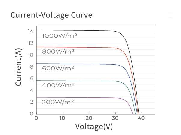
- Current Rise as Voltage Lowers (and vice-versa): This refers to the I-V curve of a solar panel.
- As you move away from the Maximum Power Point (MPP) towards lower voltages (e.g., by increasing the load), the current initially rises.
- Conversely, if the voltage increases towards Voc, the current drops towards zero.
- The inverter’s MPPT constantly tracks this curve to find the optimal voltage and current combination to extract maximum power.
- When an inverter current limits, it means it can no longer operate at the panel’s true Imp because that current exceeds the inverter’s maximum input current rating. In this scenario, the inverter will effectively “move down” the I-V curve to a lower voltage point where the current drawn is within its limit, thereby clipping the power.
6. Inverter Over-Temperature Protection and Back-Off
- Thermal Management: Inverters generate heat, especially when operating at high power or in high ambient temperatures.
- Derating Curves: Inverter datasheets typically include “power derating curves” based on ambient temperature. This shows how the inverter’s maximum continuous output power decreases as the ambient temperature rises above a certain threshold (e.g., 50∘C).
- Protection Mechanisms:
- Thermal Throttling/Back-off: If the internal temperature of the inverter exceeds a safe operating limit, the inverter’s control system will reduce its power output to lower the temperature. This means you get less power than the array is capable of producing.
- Shutdown: If temperatures continue to rise despite throttling, the inverter will shut down completely to prevent permanent damage.
- Location, Location, Location: This highlights the importance of installing inverters in well-ventilated, shaded areas, away from direct sunlight, to minimize thermal derating and shutdowns.
Summary of Key Design Considerations:
- Panel Pmax vs. Inverter PDC,max: Consider a slight “oversizing” of the array (e.g., 1.2:1 or 1.3:1 DC-to-AC ratio) to account for temperature derating, so the inverter is often operating near its peak efficiency, and on cooler days, it might clip, but on hot days, it will be closer to nominal.
- Inverter IDC,max vs. Panel Imp: Crucial for stringing. Ensure the sum of Imp for parallel strings (if applicable) on a single MPPT does not exceed the inverter’s limit. Modern high-current panels demand inverters with higher input current capabilities.
- Inverter VDC,max vs. Panel Voc (Cold Temperature): Absolutely non-negotiable. Calculate string Voc at the coldest expected temperature to prevent inverter damage.
- Inverter Operating Temperature Range: Understand the derating curves and ensure the inverter is installed in an environment within its specified operating limits.
- NOCT/NMOT vs. STC: Use NOCT/NMOT values for more realistic performance estimates.
- MPPT Range: Ensure the string voltage (Vmp) at operating temperatures falls within the inverter’s MPPT voltage range.
By meticulously considering these technical details, you can design a solar PV system that is not only safe and reliable but also maximizes energy harvest throughout the year, accounting for the dynamic nature of solar panel performance.
With smaller solar system the best tip id to have higher voltage and lower current which would be the same advice to campers and RV users.
No responses yet