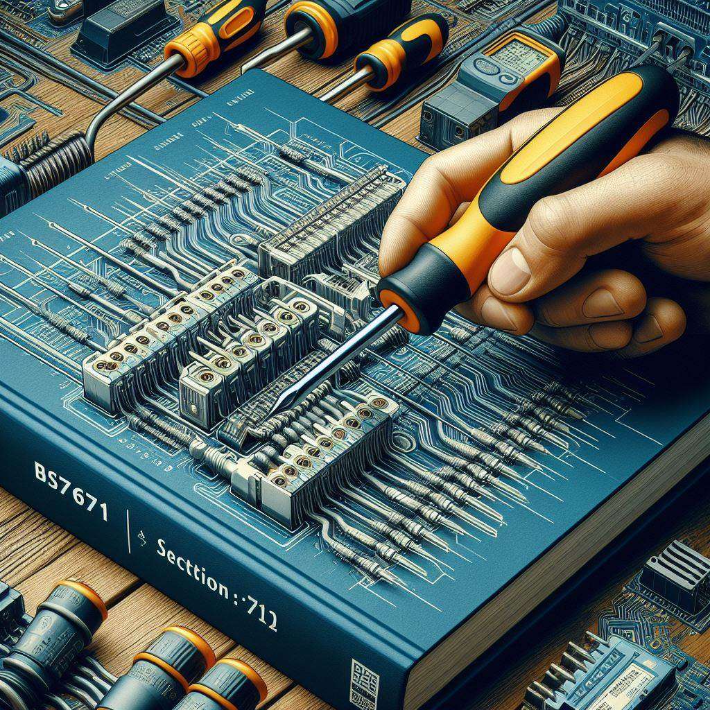
Within the British Standard BS 7671, Section 712 specifically focuses on the electrical installations of photovoltaic (PV) power supply systems. While the term “photovoltaic” refers to solar panels that convert sunlight into electricity, the principles can also be applied to some generator installations.
Here’s a closer look at what Section 712 covers:
Applicability:
- This section applies to the electrical installations of PV systems, including those with AC modules (modules that generate AC current directly).
- It doesn’t cover standalone PV systems (those not connected to the grid).
Important Considerations:
- Terminology and Notation: Section 712 establishes specific terminology and notation used throughout the section to ensure clear communication regarding PV systems.
- System Design: While not providing a full design guide, it highlights the importance of considering various factors during system design, such as:
- Earthing arrangements
- Protection against fault currents
- Isolation and switching
- Metering
Connection to Low-Voltage Installations:
- This section outlines essential requirements for connecting PV systems to low-voltage installations (typically the electrical system in your home or building). Here are some key points:
- Protective device coordination: Ensuring appropriate fuses and circuit breakers are in place to protect the system in case of faults.
- Isolation and switching: Requirements for isolating devices (like DC isolator switches) to disconnect the PV system for maintenance or emergencies.
- Additional protection: The need for RCDs (residual current devices) in some cases for added safety.
- Earthing and bonding: Proper earthing arrangements to minimize the risk of electric shock.
712.411.3.2.1.1 On the AC side, the PV supply cable shall be connected to the supply side of the overcurrent protective device for automatic disconnection of circuits supplying current-using equipment.

Informative Content:
Section 712 also includes informative content that doesn’t necessarily have mandatory requirements but provides valuable guidance:
- Risks associated with PV systems, such as DC currents and potential arcing faults.
- Recommendations for minimizing these risks through proper design and installation practices.
- AFD and SPD use and requirements and recommendations.
Recent Amendments:
It’s important to note that Section 712 has undergone significant revisions in recent amendments to BS 7671, particularly Amendment 2 published in March 2022. These revisions include:
- More detailed requirements for earthing and bonding
- Information on voltage optimizer technologies used in some PV systems (rapid shut down)
- Expanded coverage of inverter connections
In the BS 7671:2018+A2:2022 standard, there have been significant changes regarding surge protection requirements. Let’s look into the details of inverter connections:
- Surge Protective Devices (SPDs): In the previous edition of BS 7671 (specifically, BS 7671:2018+A1:2020), surge protective devices took center stage. However, there was some confusion about which SPD type to use, where to install them, and how to comply. The National Committee, JPEL 64, received feedback that SPDs should be mandatory unless a specific client explicitly declined them.
- Simplified Approach: The National Committee listened to this feedback and simplified the requirements. In BS 7671:2018+A2:2022, the regulation 443.4.1 was modified. The complex risk assessment, the Calculated Risk Level (CRL) factor, and the greyscale map of the UK were removed. Instead, the standard now states that protection against transient overvoltages must be provided where the consequence caused by overvoltage could:
- Result in serious injury to, or loss of, human life.
- Result in failure of a safety service (as defined in Part 2).
- Result in significant financial loss or data loss.
- Client Refusal: If none of the above conditions apply, SPDs should still be fitted unless the installation owner explicitly declines such protection. The owner can accept the risk of damage to both wiring and equipment as being tolerable. This client refusal caveat is now available for domestic, industrial, and commercial installations. If a client refuses SPDs, it’s advisable to obtain their refusal in writing along with an explanation of the benefits and consequences
Overall Significance:
Understanding Section 712 of BS 7671 is crucial for qualified electricians working on solar panel installations. It provides a framework for safe and compliant electrical connections between PV systems and your building’s electrical system.
Earthing and Bonding Requirements for Solar Panel Systems in BS 7671 – Section 712
While BS 7671 doesn’t provide an entire chapter dedicated to earthing and bonding, Section 712 offers crucial details on these aspects specifically for solar photovoltaic (PV) systems. Here’s a breakdown of the key requirements:
Earthing:
- ( Purpose): The primary objective of earthing in a solar PV system is to:
- Minimize the risk of electric shock by ensuring conductive parts of the system are at or near earth potential.
- Provide a path for fault currents to flow safely in case of an electrical fault.
- Earthing Arrangements: Section 712 doesn’t mandate a specific earthing arrangement. However, it highlights two common options:
- TN-S System: This is the most common earthing arrangement in the UK for low voltage installations. It uses separate conductors for protective earth (PE) and neutral (PEN). In a TN-S system for PV, the metal frame of the PV array is typically bonded to the main earthing terminal of the building.
- TT System: Less common in the UK, this system uses a local earth electrode for earthing. In a TT system for PV, the metal frame of the PV array can be bonded to the local earth electrode.
Bonding:
- (Purpose): Bonding connects all exposed conductive parts of the PV system together at equipotential, minimizing voltage differences and the risk of electric shock.
- Bonding Requirements: Section 712 emphasizes the importance of bonding the following:
- The metal frame of the PV array
- The DC side of the inverter enclosure
- All exposed conductive parts associated with the DC cabling
Additional Considerations:
- Earthing Impedance: The earthing impedance (resistance) of the earthing system needs to be low enough to ensure effective fault current flow. Specific values might be outlined in the manufacturer’s instructions for the PV system.
- RCD Protection: In some cases, using an RCD (residual current device) on the AC output of the inverter can provide additional protection against earth faults. Section 712 doesn’t make RCDs mandatory for all PV systems, but it highlights situations where they might be necessary.

Solar installation kit £4000 delivered
In the context of BS 7671:2018+A2:2022, the recommendations regarding earthing arrangements for solar panels are essential for ensuring safety and proper functioning. Let’s explore the relevant guidelines:
- Earthing Systems in BS 7671:
- The standard lists five types of earthing systems:
- TN-S: Separate neutral and protective earth.
- TN-C-S: Combined neutral and protective earth.
- TT: Separate neutral and protective earth with local earth electrodes.
- TN-C: Combined neutral and protective earth (not commonly used).
- IT: Isolated system where the source is either connected to earth through a deliberately introduced earthing impedance or is isolated from Earth1.
- The choice of earthing system depends on the specific installation and safety requirements.
- The standard lists five types of earthing systems:
- Solar Array Grounding:
- For land-based photovoltaic (PV) installations:
- Connection to Earth: It is not recommended to connect any of the current-carrying DC conductors to Earth.
- Exception: Earthing of one of the live conductors on the DC side is permitted if there is simple separation between the AC and DC sides.
- Functional Earth: If a functional earth is required, it is preferable to consider the part as isolated from Earth (not an extraneous conductive part). However, if the resistance reading is less than 22 kΩ, the part is considered extraneous, and protective equipotential bonding (as required by BS 7671) should be applied2.
- For land-based photovoltaic (PV) installations:
- Protective Measures:
- Ensure that the installation adheres to the relevant earthing system and that any earth electrodes are correctly installed.
- Follow the guidelines for protective conductors, bonding, and equipotential bonding to prevent electric shock hazards and ensure proper functioning of the PV system
Isolation and Switching Requirements for Solar Panel Systems in BS 7671 – Section 712
Section 712 of BS 7671 emphasizes the importance of isolation and switching devices in solar photovoltaic (PV) systems. These devices allow for safe disconnection of the PV system for maintenance, emergencies, or when working on other parts of the electrical installation. Here’s a closer look at the key requirements:
Isolation Devices:
- Purpose: Isolation devices are essential for isolating the DC (direct current) circuit between the PV array and the inverter. This ensures personnel safety during maintenance, troubleshooting, or emergencies.
- Mandatory Requirement: Section 712 mandates the use of a suitable DC isolator switch to disconnect the DC circuit. This switch must be:
- Located where it can be easily accessed and readily operated by emergency personnel. Ideally, this should be near the inverter location but accessible from outside the building in case of a fire.
- Clearly labeled to indicate its function (e.g., “Solar PV Isolator”).
- Capable of carrying the maximum DC current of the PV array.
- Listed as suitable for DC isolation of PV systems according to relevant standards.
Additional Considerations:
- AC Isolation: While not always mandatory, BS 7671 recommends having an additional isolation switch on the AC (alternating current) output of the inverter. This provides an additional layer of safety during maintenance or emergencies. Similar to the DC isolator, the AC isolation switch should be appropriately rated and labeled.
- Multiple DC Isolators: For larger PV systems, Section 712 allows for the use of multiple DC isolator switches to isolate different sections of the PV array. This can be beneficial for maintenance purposes.
- Manufacturer’s Instructions: Always refer to the manufacturer’s instructions for your specific PV system, as they might recommend additional isolation devices or specific switching procedures.
Types of Isolation Switches:
- Disconnectors: These are simple on/off switches that manually disconnect the circuit.
- Circuit Breakers: These can act as both isolation and protection devices, interrupting the circuit in case of a fault current. However, they might not be suitable for all PV systems.
Importance of Proper Isolation:
Having properly installed and functional isolation devices is crucial for the safety of anyone working on the solar panel system or the connected electrical system. By ensuring the DC and potentially AC circuits can be safely isolated, the risk of electric shock is significantly reduced.
Returning to the context of BS 7671:2018+A2:2022, the recommended location for isolator switches in solar installations depends on the specific components and their purpose. Let’s explore the relevant guidelines:
- AC Isolator for Inverters:
- When dealing with solar photovoltaic (PV) installations, a local isolator switch should be installed adjacent to the inverter(s). This serves two essential purposes:
- Maintenance: The isolator allows easy access for maintenance of the AC cable run and the inverter(s).
- Testing and Inspection: Having an isolator near the inverter(s) facilitates testing and inspection up to the panels.
- This practice complies with the requirements of BS 7671, but it’s also considered industry best practice1.
- When dealing with solar photovoltaic (PV) installations, a local isolator switch should be installed adjacent to the inverter(s). This serves two essential purposes:
- Surge Protection Device (SPD) Location:
- The surge protection device (SPD) that protects the inverter must be positioned within 10 meters of the inverter.
- If achieving this proximity at the incoming mains/grid supply metering point or the source of the circuit is not feasible, an additional SPD should be installed close to the inverter2.
- Emergency Switching:
- Emergency switching is crucial for isolating any part of an installation swiftly in case of unexpected danger.
- For installations with rotating machinery, emergency switching is typically done using “stop” buttons.
- These stop buttons should be located near the machine or equipment to ensure quick access and response
- It should be noted that if there is a fire, can the isolators be reached, for example at a battery fire. it has been mentioned that external shut down should be in place.
ADDITIONAL information as to the common topic:
The Book REGS:
The 17th edition (in 2008). 551.7.2
If a generating set is installed on an existing/non-dedicated circuit then the following additional conditions must be met for the installation to be compliant:
(i) the current carrying capacity of the final circuit conductors shall be greater than or equal to the rated current of the protective device plus the rated output of the generating set, and
(ii) A generating set shall not be connected to a final circuit by a plug and socket, and
(iii) A residual current device providing additional protection of the final circuit in accordance with Regulation 415.1 shall disconnect all live conductors including the neutral conductor, and
(iv) The line and neutral conductors of the final circuit and of the generating
set shall not be connected to earth, and
(v) Unless the device providing automatic disconnection of the final circuit in accordance with Regulation 411.3.2 disconnects the line and neutral conductors, it shall be verified that the combination of the disconnection time of the protective device for the final circuit and the time taken for the output voltage of the generating set to reduce to 50 V or less is not greater than the disconnection time required by Regulation 411.3.2 for a final circuit.
Notes were added to Regulation 551.1
the procedure for connecting generating sets up to 16 A in parallel with the public supply is given in The Electricity Safety, Quality and Continuity (Amendment) Regulations 2006. For sets above 16 A the requirements of the distributor must be ascertained. The 17th Edition recognizes that there are two connection options:
(i) Connection into a separate dedicated circuit
(ii) Connection into an existing final circuit
Connection into a dedicated circuit is preferred.
Regulation 551.7.2 sets out the requirements for the two options. The Regulation requires that a generating set used as an additional source of supply in parallel with another source shall either be installed on the supply side of all protective devices for the final circuits of the installation
or if connected on the load side of all protective devices for the final circuits must fulfil a number of additional requirements. (see below)
The 18th edition 2021:
551.7.2 A generating set used as an additional source of supply in parallel with another source shall be installed:
– on the supply side of all the overcurrent protective devices for the final circuits of the installation, or
– on the load side of all the overcurrent protective devices for a final circuit of the installation, but in this case all the following additional requirements shall be fulfilled:
(i) The conductors of the final circuit shall meet the following requirement:
Iz ≥ In + Ig
Where:
Iz is the current-carrying capacity of the final circuit conductors
In is the rated current of the protective device of the final circuit
Ig is the rated output current of the generating set
(ii) A generating set shall not be connected to a final circuit by means of a plug and socket-outlet
(iii) The line and neutral conductors of the final circuit and of the generating set shall not be connected to
Earth
(iv) Unless the device providing automatic disconnection … ( same as previous)..
551.7.2(1): (i) the current carrying capacity of the final circuit conductors shall be greater than or equal to the rated current of the protective device plus the rated output of the generating set.
4 Responses
this page has been updated to give some insight into the electrical safety of the installation of solar.
feel free to register on the forum to talk shop…
Regulation 712.443.101 Where protection against transient overvoltage is required by section 443, such protection shall also be applied to the DC side of the PV installation. When the inverter incorporates an SPD, it is only considered as fulfilling the SPD requirement if the manufacturer specifies its use for the DC side of the PV installation. Otherwise, it will need an external SPD. Varistors included in the inverter are not considered an SPD. This will mean that if the electrical installation requires surge protection to be fitted to comply with section 443, as discussed above, SPDs would now also need to be installed on the DC side of the installation to protect both the PV panels and the inverter. Surge protection devices designed for use on the DC side of a PV system are designed to a different standard than SPDs used in low-voltage installations. Although they are still described by using type 1 and type 2, as explained above, where type 1 devices are to protect against direct lightning, it is extremely important that only devices designed for use on the DC side of a PV installation are used. All SPDs installed on the DC side of a PV installation should comply with BS EN 61643-31. Generally, the SPD will be a Type 2, unless the building has an external lightning protection system.
Copyright Checkatrade. Using this information in an article or blog? Please add a link back to https://www.checkatrade.com/blog/trade/technical-advice/amendment-2-wiring-changes/
The question and reference to this page, is rather large. the article does NOT cover everything.
Remember inverters can offer TNS but are largely TT systems. You would install off or on grid in the same way that you would a grid supply.
AFD – install on the solar PV , this can occur as a major problem to solar panel roof fires. this may be built into the inverters.
Disconnect and breakers DC.
Ensure that the rated power and curve can support the normal operation of the inverter basic ohms law will address current over the DC battery cables. – take note as not all battery modes will run full power.
You should use a disconnect, which can be the breaker. All DC cables SHOULD have a suitable breaker.
Fault tolerance on load sharing.
currents are not equally shared on load sharing, where you would have more than one battery, therefore the protection should be rated at the individual battery current on the inverter load.
You could use a lower rating if you wanted to reduce operating in what could be fault conditions.
This condition would not be critical, for example capacity issues, cell fault, battery management fault, a fire or short.
it is not recommended to install a battery without a breaker. Many of the older designs did not have a on battery breaker, most of the new batteries do have breakers integrated. breakers or fuses should be At the battery.
[…] an installation of any solar system. You can find out more about the electrical requirements here:Delving into BS 7671: Section 712 and Solar Panel Systems — RenewSolarWithstanding that the information does not cover what a DIY’er can or cant do and if you […]