Wiring Solar is very different to most home wiring, if you have tried to call an electrician out for your solar then you may find you have been far pushed to find one.
The issue here is that most trained for AC systems and most of the solar installations are DC.
We are not “at that same level” until to get up to Grid engineers. But there has been a lot of “training courses” for children to learn some bits and spout marketing waffle that’s usually wrong, and there are some legal restrictions.
Solar installations are easy to break into 3 parts:
1.The Solar panels, DC, Always on.
2. Battery system – Specialist normally Low voltage, could kill.
3. Inverter – changes DC to AC, charges the battery and supplies the home – Lots of different versions.
Solar panels themselves are not deadly (some can be) because the voltage is too low with a single panel, but when there are two, they are dangerous. Fusing solar panels is a bit of a oddity and the power they make crashes at the same output current, this does not mean that there are many dangers.
Arc faults happen, this can be a bad connection or mixed connection on each of the panels or wear.
This is why we see roof fires.
Its is when you come to parallel your solar panels that a fuse is essential. – use T class fuses. – use AFD.
Solar batteries hold a lot of power and can deliver massive currents, there are some myths around the need to have big and costly fuses with large gaps. The problem is what is called a Slow Short. This allows the arc to bridge as short and a fuse.
Most batteries have a built in breaker which is secondary to the BMS protection (over current) however it is fairly common to see bad wiring/installation where the fuse/breakers are not near enough or between parallel batteries. We would recommend having a master and slave fuse/breaker system in addition to the BMS.
It is a good idea to load limit the rating of the fuses.
If you are installing solar and a battery the fuse rating should be that of the inverter nominal output. The type class of breakers tend to allow for surges. You would want to protect the cable and the hardware but limiting to the current expected. This plays a larger part in multi battery installations, for example a 5kw inverter on a 48V system will use a current of 104 amps on a single battery, and two batteries in parallel will use a current of 52 amps, and four would be 26 amps
Therefore rather than using a 35mm cable, we can use 25mm cables, but we would not want to drop to 6mm due to the way that multiple battery installations charge and load balance.
While AC will pull around 21amps, it is important to review the charging set up. Some of our large inverters have a charge current of 190 amps, while this would appear to to be split between the packs, it is not often the case over time as there is Battery Drift. If you have weaker cells, or different resistance in the pack and in the cable, then the voltages will drift and the BMS may command charging at different levels. This can lead to over current if you are using small cables and lower rating breakers.
While batteries should be charged low and slow. Not everyone takes notice of this information and tries to charge in the shortest time at the highest power. Especially those with Cheap rate time slots in winter.
Charge windows can be as little as 4 hours.

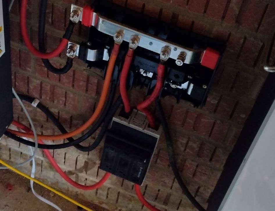
You may have notice in the images that there are two different types of fuses used, the main image shows a Keto T class and the lower, does not have the breakers in, but would be the din type breakers.
Cables – a nightmare.
Cables carry the current of any system and the cable is made of three parts, the wire and insulation as well as the connection. They can be rated differently while most will use the square mm to to rate the cable.
For example: our 25mm is rated at 270amps, Rule of thumb is 100amps. Cables I have also seen of 25 and 35mm2 I have rated them to 70 amps. while they were claimed to be 300. Oddly from a “reputable supplier”.
A very common issue I have seen is connections the cheaper (thinner) lugs tend to rely on the mount for load carrying. where as we only use British standards, which are around twice as thick, I should really show a picture of the two.
Along with the connection is the bus bar!
A bus bar is a wire block where you can connect multi cables in and out. ( image shows the Victron energy distro).
A common danger which I have seen countless times are these bus bars that claims to be 250 amps. while the bar technically is the fixing lugs are only rated for 65 amps, with many being less that 30 amps.
The Victron lynx is rated to 1000amps and at £100+ is is a costly part.
Our preferred bus bars, not so smart looking as the Victron, are rated to 400amps but only costs £45.
These allow for many connections to be made with M10 connection lugs.
Our Mini Bus bars (Bus hubs) Are rated to 200 amps and are £15. These are great for 3 way or 4 way only with stack M12 layouts.
ALL JOINS Should be inspected with a load test for 20 minutes and check once a year.
At RenewSolar we supply a wide range of cables, breakers and fuses. They are a good price and we have used them, test them and install them.
We do not list all our hardware in the shop, and it is a good idea to contact us for the best solution.
2 Responses
Dear Renewsolar,
I am reaching out to inquire about your company’s current capacity availability, as we have an upcoming project for which we’d like to request a quotation. We’d appreciate your feedback on feasibility and timelines.
Please let us know if you require any additional details to provide an estimate. We look forward to your response.
Best Regards
George silver
Hello George,
While you see from the website that we are more domestic, we also offer trade and commercial. Our capacity is in GWh We have both UK and Euro based businesses and companies which gives us a competitive edge in terms of delivery and scales for both domestic and commercial implementations.
We lever our international trade partners to provide a fast solution and also large scale rolls outs in reasonable time scales to meet project deadlines.
We also offer project management, this can be for all projects and can be a hands – off for clients where you simply say the finality of the project and results you desire and we will complete; On time and usually under budget!
If you would like more information, drop us an email and outline of what you were looking for.