electrics tend to be made fearful, but they are not, they can kill you but so can life. building your own inverter and getting to know how things work is a great way to understand what you are buying, how to fix it and how it works. Its usually more fun to build your own and to spec it just how you want.
Building a square wave inverter using a 555 timer IC is a moderately complex project that requires a good understanding of electronics. Here’s a high-level overview of the steps and components you’ll need:

Components:
- 555 Timer IC
- Resistors (various values for setting up the frequency)
- Capacitors (for timing and filtering)
- Potentiometer (for frequency adjustment)
- MOSFETs or Transistors (for switching the current)
- Transformer (to step up the voltage)
- Diodes (for protection and rectification)
- Power supply (source of DC voltage)
Steps:
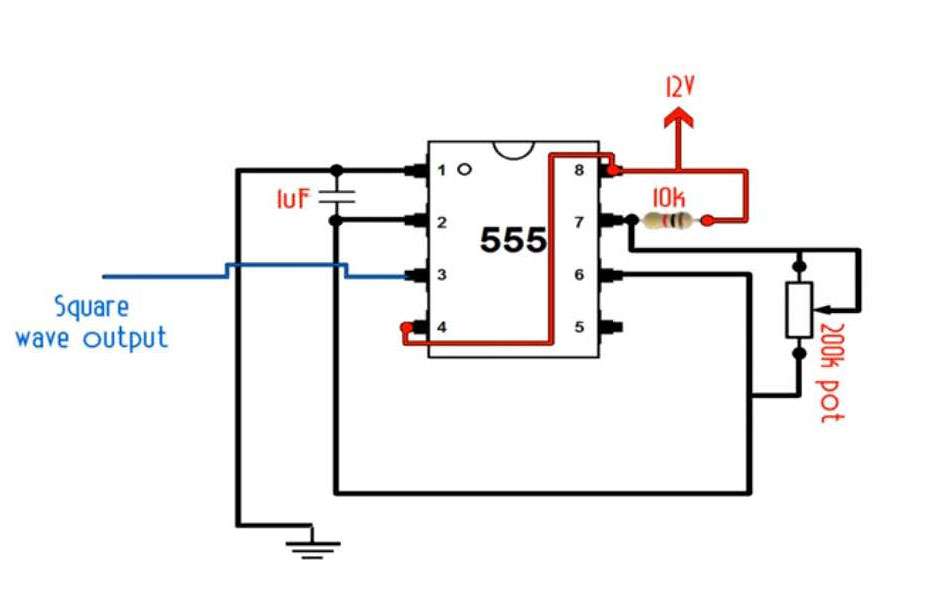
- Design the Oscillator Circuit: Use the 555 timer in astable mode to generate a square wave. KIT
- Set the Frequency: Adjust the resistors and capacitors to set the frequency of the square wave to match the desired output frequency (50Hz or 60Hz).
- Amplify the Signal: Use MOSFETs or transistors to amplify the square wave to a higher current suitable for driving a transformer.
- Step-up the Voltage: Use a transformer to step up the voltage from the low-voltage DC source to 230V AC.
- Filter the Output: If necessary, add filters to smooth out the waveform.
- Test and Debug: Carefully test the inverter with a low-power load before connecting to any significant appliances.
Remember, working with high voltages can be dangerous, so take all necessary safety precautions and consider consulting with an expert if you’re not experienced in electronics. For detailed instructions, you might want to look at specific electronics project resources or videos
2 Responses
Neat. That produces a pulsed DC output. How would one convert that into an AC output. I was thinking something like this combined with some power transistors could be used to make a desktop 12v spot welder for thin aluminium robotic skeleton construction.
Making a welder, use DC power not AC.