This tutorial outlines the construction of a solar charge controller utilizing a buck converter and a UPS module. This design provides a robust and flexible solution for managing solar power input, battery charging, and grid power integration to ensure the battery is charged and set within programmable parameters.
Components:
- Solar Panels: Sufficient wattage to meet your power needs.
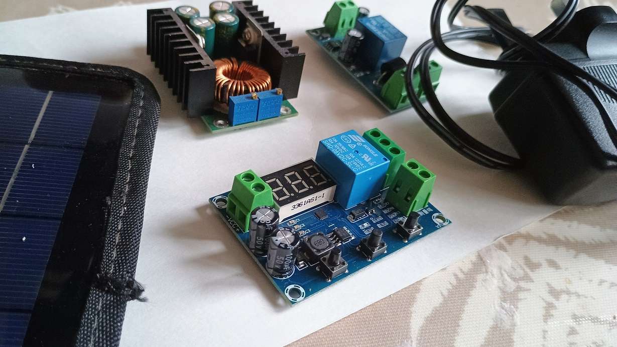
- Buck Converter: 400W buck converter capable of stepping down voltage from the solar panels to 15V or 28V.
- UPS Module: A suitable UPS module with battery charging capabilities.
- Grid-Powered AC-DC Power Supply: To provide backup power and charge the battery when solar power is unavailable.
- XH-608 Battery Monitor/Controller: To monitor battery voltage and control charging parameters.
- Battery: Appropriate size and type for your application.
- Wiring and Connectors: Suitable for the power levels involved.
- Enclosure: To protect the components from the elements.
Circuit Diagram:
Tutorial: Building a Solar Charge Controller with a UPS Module
This tutorial outlines the construction of a solar charge controller utilizing a buck converter and a UPS module. This design provides a robust and flexible solution for managing solar power input, battery charging, and grid power integration.
Components:
- Solar Panels: Sufficient wattage to meet your power needs.
- Buck Converter: 400W buck converter capable of stepping down voltage from the solar panels to 15V or 28V.
- UPS Module: A suitable UPS module with battery charging capabilities.
- Grid-Powered AC-DC Power Supply: To provide backup power and charge the battery when solar power is unavailable.
- XH-608 Battery Monitor/Controller: To monitor battery voltage and control charging parameters.
- Battery: Appropriate size and type for your application.
- Wiring and Connectors: Suitable for the power levels involved.
- Enclosure: To protect the components from the elements.
Circuit Diagram:

Building Instructions:
- Prepare the Buck Converter:
- Configure the buck converter to output the desired voltage (15V or 28V) based on your battery requirements.
- Ensure proper heat dissipation for the buck converter (fan).
- Connect a diode between the buck converter and UPS module as the UPS will back-feed.
- Connect the UPS Module:
- Connect the buck converter output to the “Battery” input of the UPS module.
- Connect the grid-powered AC-DC power supply/ Battery Charger to the “Mains” input of the UPS module.
- Integrate the XH-608:
- Connect the XH-608 to the battery terminals, one is through the relay.
- Configure the XH-608 to monitor battery voltage and control charging within the desired parameters.
The supply power of the XH608 module can be connected to the AC power input of the UPS, or connected to the battery to provide power to the device. if you are using a timer for off peak timing, then you need to connect to the battery for always on power.
- Connect Solar Panels:
- Connect the solar panels to the input of the buck converter.
- Ensure that the current and voltage output is set.
- Assemble in Enclosure:
- Secure all components within an enclosure.
- Ensure proper ventilation and cooling.
- Connect all wiring securely.
Operation:
- Solar Power: When solar power is available, the buck converter steps down the voltage from the solar panels and feeds it to the UPS module. The UPS module charges the battery via the controller.
- Grid Power: When solar power is unavailable or insufficient, the grid-powered AC-DC power supply provides power to the UPS module, which charges the battery within the set parameters of the controller.
- Connect a diode to stop power going from the UPS module back to the buck converter from the AC-DC power supply.
- Set the Parameters: You can set the voltage levels that the charging will start and stop. The “unit” is able to support 8 amps of current.
- POWER: (12v 116watts, 24v 233w) but will require a fan. The max current is 10 amps.
Safety Precautions:
- Work with DC power with caution. Always disconnect power before working on the system.
- Use proper safety equipment, such as insulated tools and gloves.
- Ensure adequate ventilation to prevent overheating.
- Follow all manufacturer’s instructions for each component.
- Remember to use fuses and isolator switches.
Notes:
- This is a basic design and has current limits, do not exceed 8 amps.
- Consider adding features such as overcurrent protection, temperature monitoring, and remote monitoring capabilities.
- Thoroughly test the system before connecting it.
Disclaimer: This tutorial is for informational purposes only. The author assumes no responsibility for any damage or injury resulting from the construction or use of this project.
Go to our shop for a hardware package for this project.
You can swap out the buck converter in this project for a MPPT charge controller. We also have a project to build your own MPPT charge controller.
One response
Swap the AC side feed ( grid powered dc) and solar input which is shown in the wiring diagram.
the Diode will now be placed on the AC feed (where is is) to stop solar pushing power back to the power brick.
The ups system is a AC fall over back up to the battery, therefore the primary feed should be solar and not grid power.
The grid power needs to be on when solar is off to maintain the battery.
DO NOT LOOP the systems – Off grid system putting out AC power to a power brick, that is charging the battery, thats running the off grid system.