When people begin using solar power, the starting point can vary. It often begins with solar lights and improving their performance beyond the factory settings, which can escalate to powering an entire off-grid home.
About five years ago, I completed a small project using a security camera. Inside the case, there are two 6-watt solar panels, a 30 Ah LiPo battery, a charge controller, and a battery BMS, along with a voltage regulator for the output power.
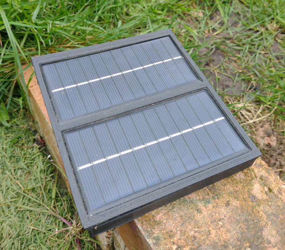
The case was 3D printed, which was straightforward and quick to produce. Conveniently, the battery was almost the same size as the panels, but ultimately, the larger of the two dictates the case size, whether it’s the panels or the battery.
The solar panels are 6V and 6W (peak), and I configured them in parallel to maximize power output, which is significantly more than what the camera consumes. The battery has a capacity of 111Wh, and the camera uses 0.2Ah or 0.66Wh, allowing for a runtime of over 73 hours without recharging.
Ensuring a dry case for the electronics was a challenge, so I sealed it with foam tape for easy disassembly. The panels were affixed with G119 adhesive, the same type used for car windshields.
The charge controller is fairly standard; the panel voltage matches the TP4056 specifications, which includes input and output current protection. Additionally, there’s a backup charging port via a micro USB connection.

The circuit includes a BMS to safeguard the battery against overcharging and discharging. With no MPPT or PWM function the charge output voltage (4.2v) would remain the same and the current would vary due to the nature of solar.
The output power.
Power regulation is one of the quandaries of power to power loss and battery conversions as well as voltage range. For my project I needed to have a 3.3v output, the battery of course ranged from 4.2 to 2.5 While the cut off protection would address the battery, the need to buck ( lose voltage) and boost ( gain voltage) means that you have in effect two processes that are the opposites.
The easy solution would be to use a higher voltage, for example two lipo batteries in series giving us a range of 8.4 to 5v’s this way we are just bucking power down to the right voltage.

The problem here is of course that when we are using 1S 2P we have to consider the drop out voltage,
The dropout voltage of a voltage regulator refers to the minimum voltage difference between the regulator’s input and its output voltage. This difference is necessary to maintain regulation and enable the regulator to provide its rated voltage and current. Let’s delve into this concept further:
- Voltage Regulators:
- A voltage regulator is a device that accepts an input voltage and regulates it down to the output voltage it is rated for.
- For instance, consider the LM7805 voltage regulator, which outputs 5 volts.
- However, to provide this 5-volt output, it needs to be fed a higher voltage as its input.
- Dropout Voltage:
- The dropout voltage is the additional voltage required above the rated output voltage for the regulator to function correctly.
- In the case of the LM7805, it needs at least 2 volts higher than the 5 volts to deliver the desired output.
- Thus, its dropout voltage is 2 volts, as 5 volts + 2 volts = 7 volts.
- Heat Dissipation and Efficiency:
- While voltage regulators can withstand higher input voltages, the difference between input and output voltage results in heat generation.
- Excessive heat can lead to regulator malfunction or damage.
- It’s recommended to follow the dropout voltage specified by the manufacturer in the datasheet.
- Ideally, the input voltage should be limited to 3 volts higher than the output voltage to strike a balance between efficiency and heat dissipation.
Remember, the dropout voltage is crucial for keeping the input voltage within the right range and ensuring proper regulation of the output voltage. If we go back to the 2S 1P battery configuration, then we have 8.4v to 7 volts to work with from the pack., but many will know that the voltage would drop to around 7.2v very quickly; meaning for 5 volts we have little power to work with.
The Mini360 DC-DC Buck Converter is a compact and efficient module built around the MP2307 from Monolithicpower. Let’s explore its key parameters:
- Input Voltage Range:
- The Mini360 accepts an input voltage range of 4.75V to 23V DC.
- Output Voltage Range:
- It can output an adjustable DC voltage within the range of 1V to 17V.
- Maximum Continuous Current:
- The recommended maximum continuous current for the Mini360 is 1.8A.
- Surge Current:
- It can handle a surge current of up to 3A.
- Efficiency:
- The module achieves a maximum conversion efficiency of 95% (at 5V input and 3.3V output with ~200mA load).
- Quiescent Current at Different Voltages:
- The quiescent current varies with the output voltage:
- 1.8V and 2.5V: Below 0.4W quiescent
- 3.3V and 5V: Around 0.5W quiescent
- 12V: Approaches 0.9W, which means the module can get noticeably hot even when idling.
- The quiescent current varies with the output voltage:
As we can see the issue with this IC is that the power requirement is above that of the battery, and therefore difficult to use in this use case. So I have two options…..

Here we see a simple HT7333 ic (left) and the MT3608 (right).
The HT7333 is a high-efficiency 3.3V linear voltage regulator manufactured by Holtek Semiconductor Inc. Let’s explore its key specifications:
- Voltage Regulation:
- The HT7333 provides a regulated output voltage of 3.3V.
- It achieves this with very low losses due to its low quiescent current and low dropout voltage.
- Input Voltage Range:
- The maximum input voltage it can handle is 12V.
- Quiescent Current:
- The quiescent current (current leakage when no load is connected) is only 8μA for the HT7333.
- Package Options:
- The HT7333 is available in 3-pin TO-92 and SOT-89 packages.
- Applications:
- This voltage regulator is commonly used in applications where a stable 3.3V supply is required, such as microcontrollers, sensors, and low-power devices.
The MT3608 is a versatile step-up (boost) DC-DC converter module designed for small and low-power applications. Let’s explore its key features and specifications:
- Input Voltage Range:
- The MT3608 accepts an input voltage range of 2V to 24V DC.
- Output Voltage Range:
- It can regulate the output voltage within the range of 5V to 28V DC.
- Maximum Output Current:
- The module can deliver a maximum output current of 2A.
- Switching Frequency:
- It operates at a high switching frequency of 1.2 MHz.
- Output Ripple:
- The output ripple is kept below 100mV.
- Efficiency:
- The MT3608 achieves an impressive efficiency of approximately 93%.
- Additional Features:
- Under-voltage lockout and thermal overload protection enhance safety.
- The module includes a soft start function.
- Quiescent current is minimal, peaking at 200μA.
If we look just at the Quiescent currents from both devices there is a massive difference in the idle consumption of power, while low, the MT3608 draws 25 times the power of the HT7333.
Currently, we have two methods to achieve the desired results: firstly, we can boost the voltage for the Mini360 from the battery to attain an optimal voltage range to step down to 3.3 volts; alternatively, we could utilize the HT7333. In this application, we require 3.3 volts plus an additional 170 millivolts, totaling 3.47 volts. This ensures that we harness the full power capacity from the battery.
Using the MT3608, we can use the power from the battery also to boost the voltage to 4.75volts. and then buck the voltage down to 3.3volts. here we rely on the TP4056 to halt the boost off the battery when the battery runs low. However in my project, we are losing 50% of the power to the MT3608 that would run the project. as well as the 7% efficiency loss the mini adds another 5% loss meaning that we would lose 12% of our battery capacity.. however At 5V input, the HT7333 operates with an efficiency of around just 66%.
if you would like a kit and video to follow to make you own, check out the shop as it will appear in the project section.

If you are making a USB power bank, then you should have a switch and 5 volt booster to give you the power you need.
No responses yet